Electronic Transformer Diagram For Halogen Lamps
 Electronic transformers are replaced by large transformers with steel hearts. The electronic transformer itself, unlike the classic, is a whole device, a voltage converter.
Here. Electronic transformer JINDEL (GET-03 model) with short circuit protection.
As we can see, the diagram is quite simple and collected from radios that can easily be found in any electronic ballast to feed the fluorescent lights, as well as in the lights, "conomies."
The main strengths of the diagram are the n-p-n Transistors MJE13009, which are included in the diagram. They're working in an antiphase at 30 to 35 kHz. Through them, the full load power is pumped - halogen lamps EL1. ♪ ♪ EL5. Diodes VD7 and VD8 are necessary to protect transistors V1 and V2 from reverse voltage. The symmetrical disincentor (he's a diac) is necessary to launch the scheme.
 In the Transistor V3 (2N5551) and elements VD6, C9, R9 - R11, a short-distance protection scheme has been implemented (upstream)short circuit protection)
If a short circuit breaks in the exit chain, the increased flow through R8 will result in the operation of the Transistor V3. The transistor will open and block the work of the DB3 Dissertor who launches the scheme.
R11 and C9 electrolytical condenser prevent false protection when lights are activated. At the time of switching, the filaments are cold, so the converter gives a large flow at the beginning of the launch.
A classical bridge of 1, 5-amper diet is used to straighten the network voltage 220V 1N5399♪
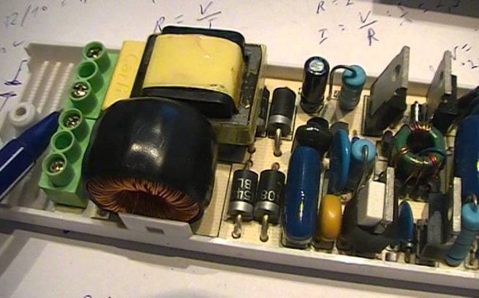
Because of its internal device, it is not recommended that the electronic transformer be switched off without load. The minimum power of the load connected is therefore between 35 and 40 watts. The body of the product shall normally contain a range of capacity. For example, on the electronic transformer hull, the first photograph indicates a range of output power: 35 - 120 watts. The minimum load capacity is 35 watts.
EL1...EL5 halogen lights are better connected to an electronic transformer with wires not exceeding 3 metres. Since the connectors leak a significant flow, the long wires increase the total resistance in the chain. Therefore, the lamps that are further positioned will be lighter than those that are closer.
It should also be borne in mind that the resistance of long wires contributes to the heating of long wires due to a significant current.


