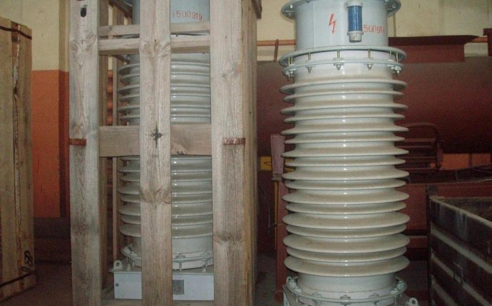
Measurement Voltage Transformers
 There are important elements of any high voltage network. Substantive appointment voltage transformers This is a reduction in the high voltage required for the supply of measuring circuits, relay chains, automatics and records (hereinafter secondary circuits). The voltage transducers measure the voltage in the high voltage grids, the feeding of the minimum voltage rolls, the protective voltages, Wattmeters, phases, enumerators, and the isolation of the network.
The voltage transducer reduces high voltage to standard 100 or 100/v3 V. and separation of the measurement chains and relay protection from the primary high voltage circuits. The one-phase voltage transducer pattern is shown in Figure 1, the primary wet is activated on the voltage of the U1 network, and the secondary hamster (U2) is connected parallel to the measuring instrument and relay. Pressure transformer, unlike The current transformer works. in a idling mode, as the resistance of parallel rolls of instruments and relays is large, and the flow they consume is small.
Figure 1. CTemperature transducer switch:
1 is the primary wet; 2 - magnetic wire; 3 - secondary
In order to feed secondary circuits, voltage transformers may be installed on both substation tyres and on each attachment. Before starting the electrical installation, the TN should be examined and the integrity of the insulation checked, the correctness of the frames and the oil level of the oil transformers should be checked. Installation, primary and secondary safety TTs shall be turned because accidental contact with welding, lighting, etc. may lead to high voltages at the primary vector ' s conclusions that are dangerous to human life. In order to maintain secondary circuits when operated safely, a secondary retread of the transformer and its hull shall be earthed. The possibility of moving high voltage into secondary circuits in the sample insulation is thus eliminated.
The nominal transformation factor is defined by:
where U1nom and U2nom are the nominal primary and secondary voltages respectively. The dispersion of the magnetic flow and cardiovascular loss results in measurement errors
As in current transformators, the secondary voltage vector will shift from the primary voltage vector to an angle of 180°. It determines the angular error.
Depending on the rated error, the classes of accuracy are 0, 2; 0, 5; 1; 3.
The error depends on the design of the magnetic wire, the magnetic permeability of steel and cosφ2, i.e. the secondary load. The construction of voltage transformers provides for the compensation of voltage errors by some reduction in the number of turns of the primary wet, as well as the compensation for angular errors by special compensating mods.


